 |
| Materials List:
270-283A Project enclosure with PC Board <1 EA> {$3.99} 276-2017 Transistor <1 EA> {$1.49} 276-2023 Transistor <1 EA> {$0.69} 273-1380 Audio Output Transformer <1 EA> {$2.99} 271-1311 100 ohm resistor <1 EA> {$0.20} 276-1122 1N914/4148-Type Diode <1 EA> {$1.29} 276-1388 2-Position PC Board Terminals <1 EA> {$0.60} 274-248 3.5mm 2 conductor panel jack <1 EA> {$2.99} |
| The power supply shown could be the battery box that comes with the prop or a wall transformer. R-S carries these also - be sure voltage matches that of the toy (battery supply). |
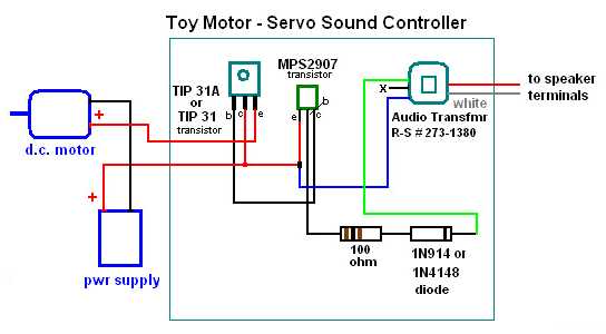
| Note in diagram above the two transistors have terminals labelled "e = emitter", "b" = base, "c" = collector. Relate these to lead diagram on the R-S package and there should be no problem in wiring them correctly. |
| Once this circuit is built, connect to positive power leads of the motor/s and power supply as shown above. Often the polarity of a toy motor doesn't matter, test this first by momentarily connecting the two leads of the motor, to the power supply directly, then reverse leads (plus/minus) if there's a difference in action - polarity matters, but usually it doesn't. |
| The RED and WHITE leads from the audio transformer are connected to the two terminals of the speaker, leaving the existing wires that power the speaker connected also. |